Download Project Document/Synopsis

Note: Induction Motor Not Included in Kit

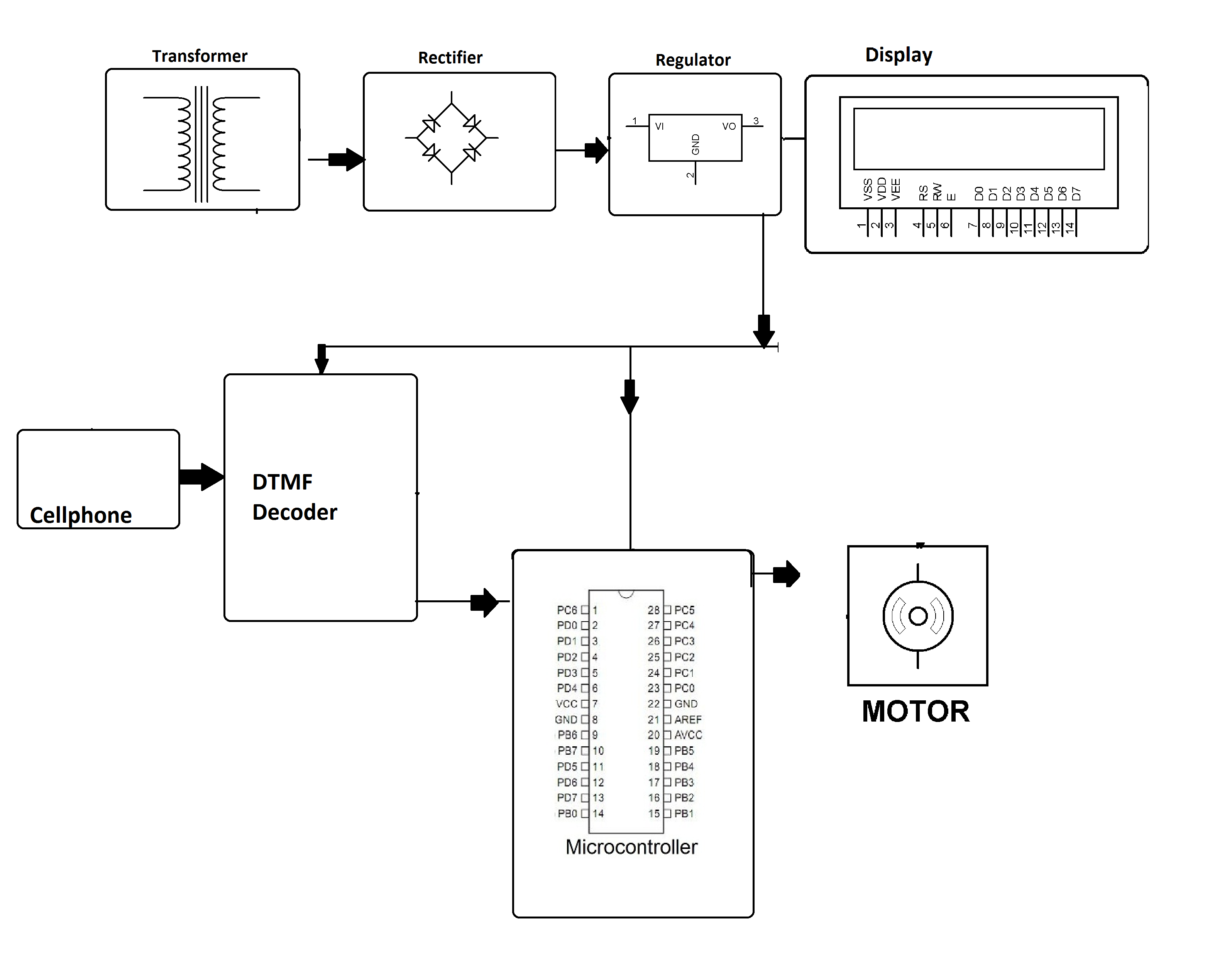
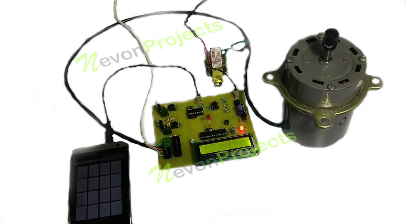
Induction motors have been used widely in different fields ranging from domestic appliances to industrial machinery. This necessitates a speed control mechanism that is efficient and is also safe to use. Also the induction motor can be run in either of the two directions which is quite useful in many applications.Induction Motor Speed And Direction Controller Project serves this purpose of controlling the speed and direction of the induction motor. Induction motor runs through direct AC line the amount of power given to it decides to what RPM it does rotates. We can modulate the power of the AC line to vary the speed of the induction motor through AC driver circuitry. An Atmega family microcontroller is used to give PWM power to an opto-coupler which drives the TRIAC giving supply to the induction motor. Instructions to the microcontroller are fed through cell phone connection to the system. The cell phone provides DTMF signals to the system which the system understands and takes actions accordingly. As per the video, a button is used to increase the speed of the motor, a button to change direction and a button to decrease speed of the induction motor. One can observe the whole process as it happens on the LCD. In this way this project proves to be quite useful in handling an Induction Motor for its speed and direction.


Hardware Specifications
- Atmega Microcontroller
- DTMF Decoder
- Induction Motor
- LCD Display
- Crystal Oscillator
- Resistors
- Capacitors
- Transistors
- Cables and Connectors
- Diodes
- PCB and Breadboards
- LED
- Transformer/Adapter
- Push Buttons
- Switch
- IC
- IC Sockets
- Software Specifications
- Programming Language: C
Block Diagram