Download Project Document/Synopsis


This project is used to control and measure the BLDC motor speed by using an IR speed sensor mechanism. There is a need for controlling a DC motor speed in industries that uses drilling, spinning, lathes, elevators etc therefore this system provides an efficient mechanism for increasing or decreasing the speed.
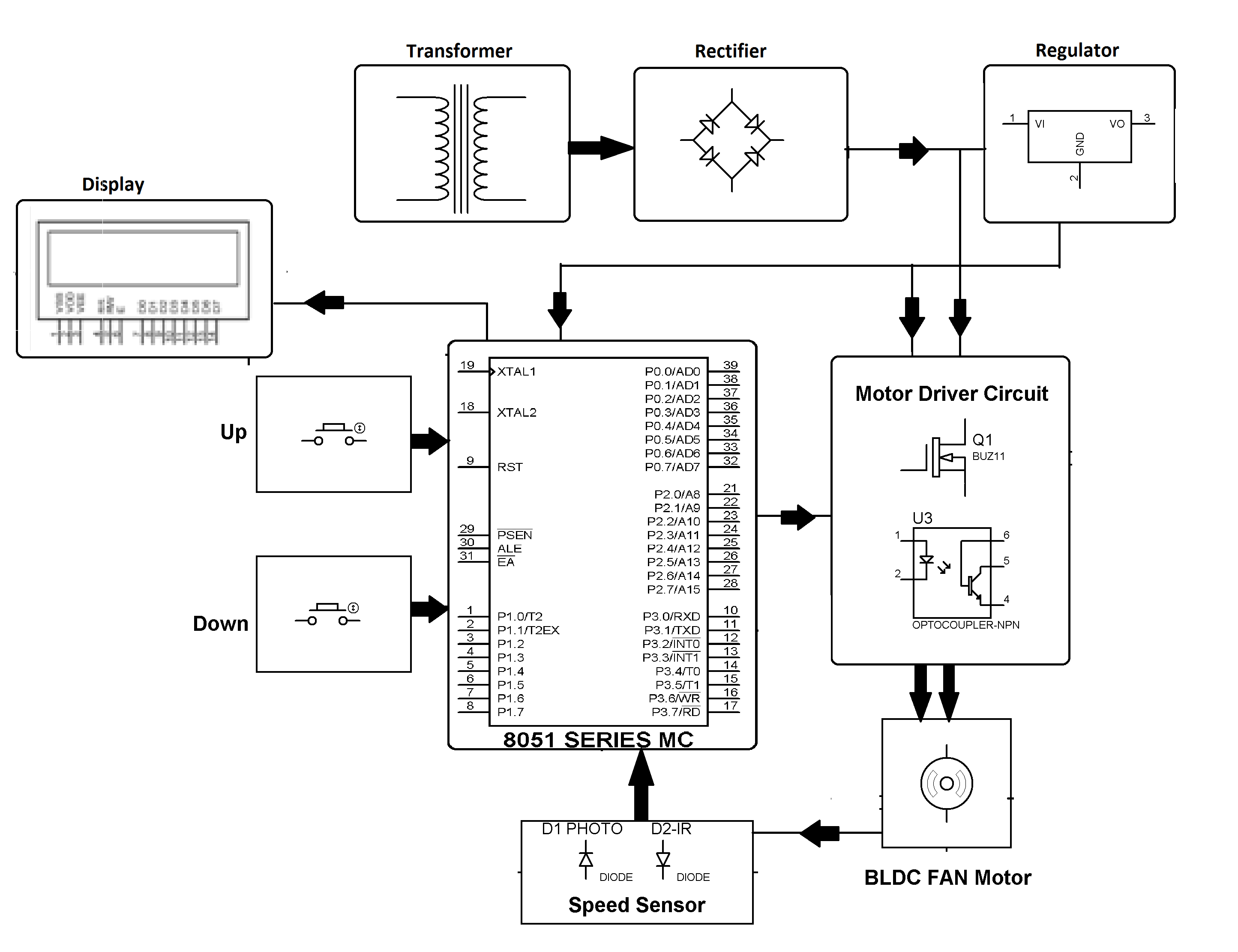
The project comprises of three phases. The first one is input phase where desired speed is entered using switches. The second phase i.e. processing enables a RPM reference of motor by interfacing IR sensor mounted on shaft and microcontroller of 8051 family in the circuit. Microcontroller generates PWM pulses according to the input or switches to regulate the supply of DC power to motor. And the last phase i.e. output uses an opto-isolator and a MOSFET for driving BLDC motor. The IR sensor measures the speed and sends it to microcontroller that displays it on LCD.


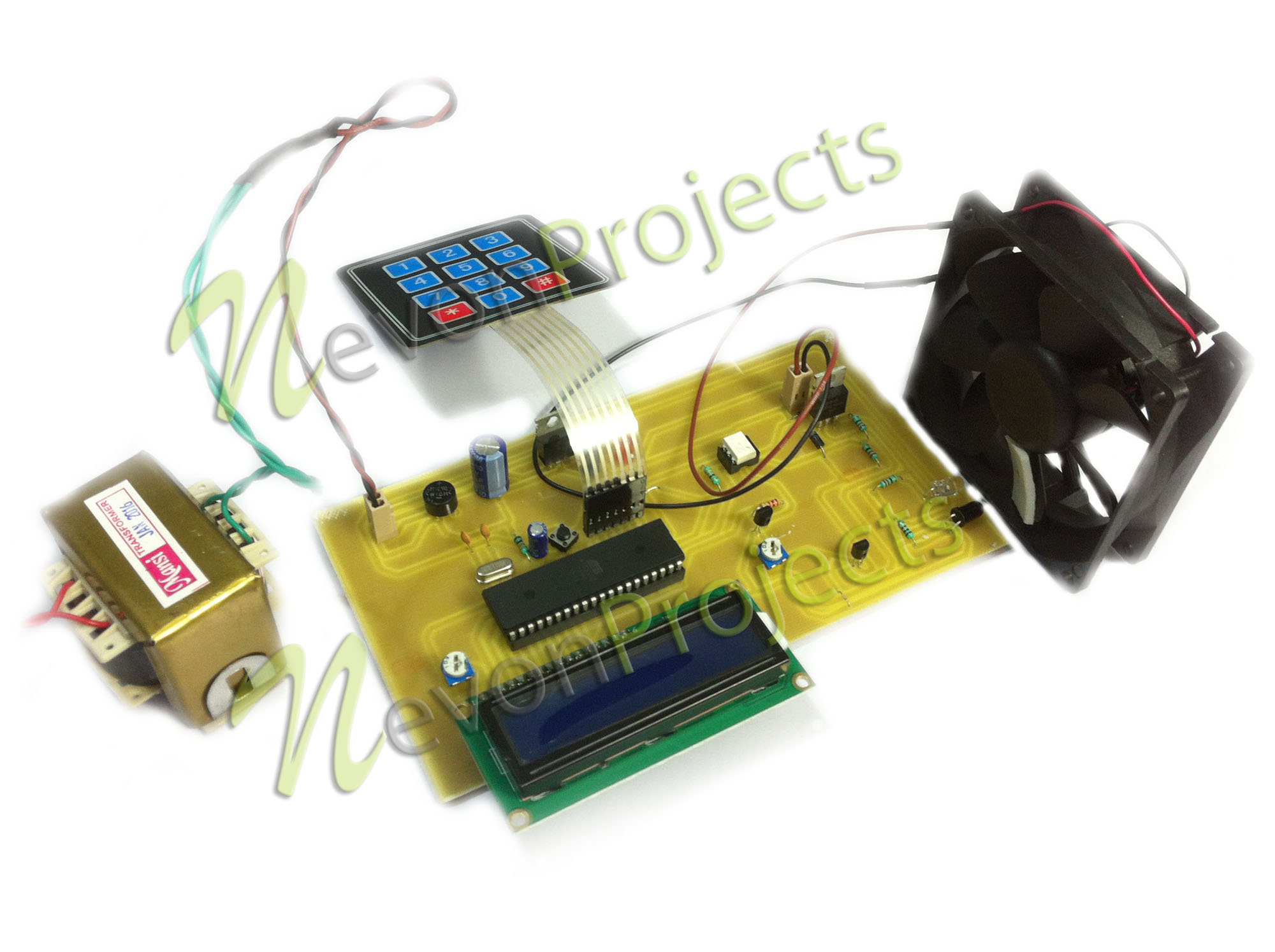
- Hardware Specifications
- 8051 Microcontroller
- Crystal Oscillator
- Resistors
- Capacitors
- Transistors
- Cables and Connectors
- Diodes
- PCB and Breadboards
- LED
- Transformer/Adapter
- Push Buttons
- Switch
- IC
- IC Sockets
- Software Specifications
- Keil µVision IDE
- MC Programming Language: Embedded C
Block Diagram