Download Project Document/Synopsis


Gearboxes or also commonly called gear reducers or enclosed speed reducers are used on many electromechanical drive systems. Gearboxes, are essentially multiple open gear sets contained in a housing. The housing supports bearings and shafts, holds in lubricants, and protects the components from surrounding conditions. Gearboxes are available in a wide range of load capacities and speed ratios.
The purpose of a gearbox is to increase or reduce speed. As a result, torque output will be the inverse of the speed function. If the enclosed drive is a speed reducer (speed output is less than speed input), the torque output will increase; if the drive increases speed, the torque output will decrease. Gearbox designs are classified as either bevel designs, where gears are perpendicular to each other, or spur designs, where two gears rotate parallel to each other.
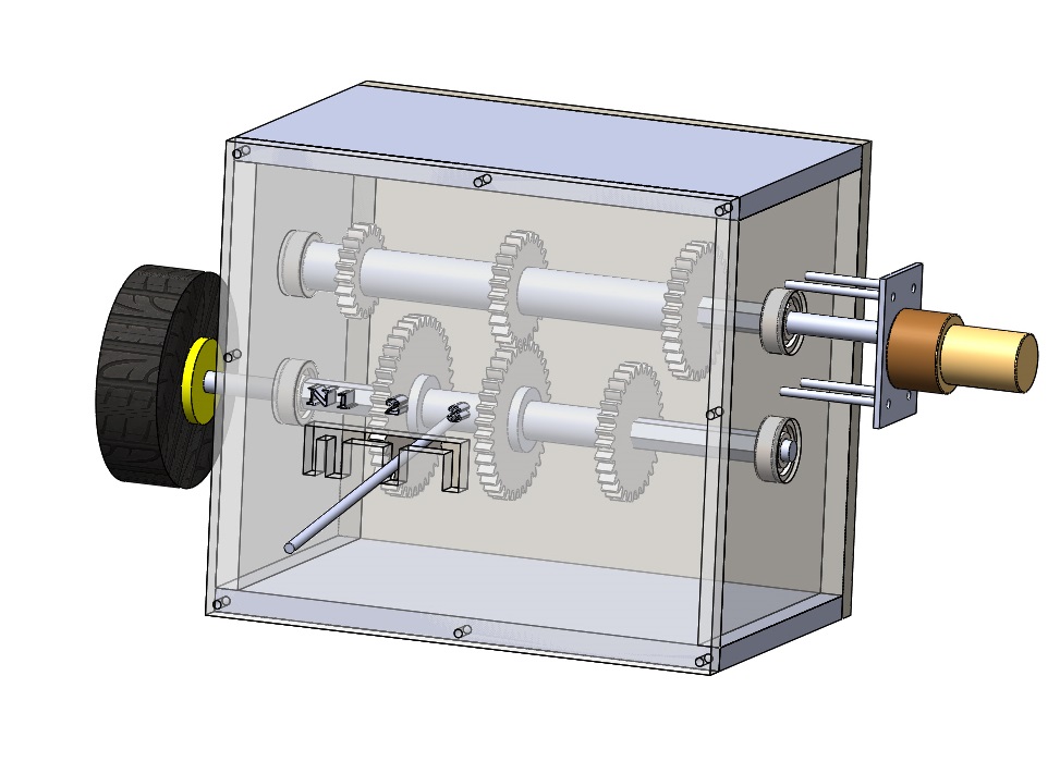
The 3 Speed Gearbox presents the mechanism of a gearbox. Gears of various dimensions are placed along the x and y axis. A motor rotates the central shaft and different arrangements that can be made in the project causes the rotational motion to transfer from one axis to other. The project is mainly made from Mdf, mild steel and Acrylic. The machine can be divided into 4 groups of gears. Each group consists of 4 gears of different dimensions. The machine works in 3 different scenarios.
In scenario 1, the central shaft is held together by a coupler. The rotational motion starts from the motor and transfers to the group 1 gears and from there, with the help of the coupler transfers to group 3 gears. In this scenario, the group 2 & 4 gears are disengaged. In scenario 2, the coupler & the group 4 gears are disengaged. The rotational motion starts from the motor and transfers to group 1 gears and from there via group 2 gears transfers to group 3 gears.
In scenario 3, the coupler & group 2 gears are disengaged. The rotational motion which starts from the motor transfers to group1 gears and from there transfers to group 3 gears via group 4 gears. The transfer of motions between groups of gears is possible due to proper meshing of biggest gears present in group 1 & 3 and smallest gears present in groups 2 & 4


- Components
- Gears
- Couplers
- Ball Bearings
- DC Motor
- Shafts
- Clamps & Mounts
- Base Frame
- Supporting Frame
Block Diagrams
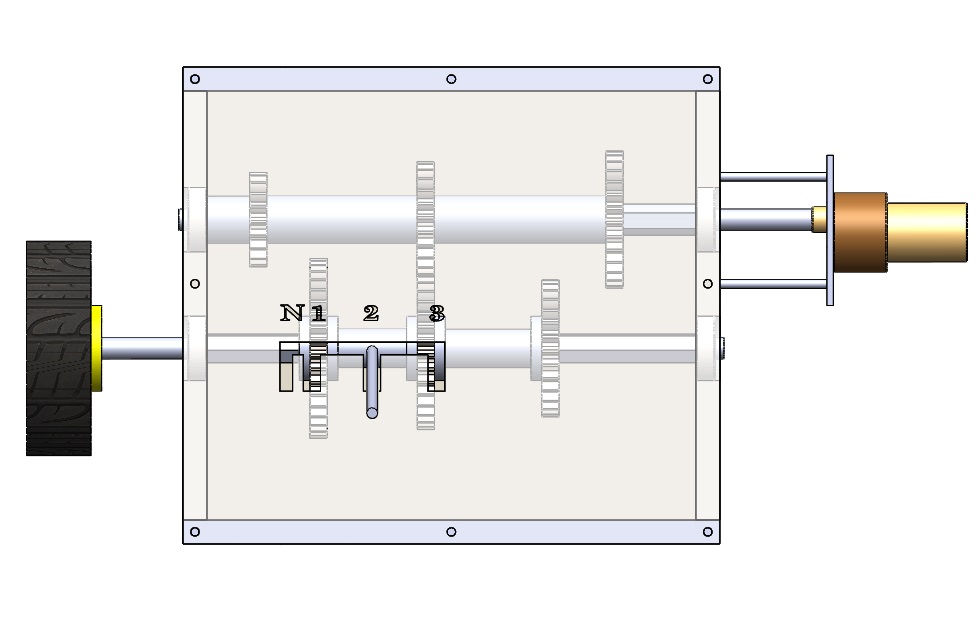
Front View
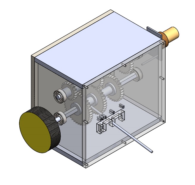
Side View